Simple FM Transmitter

Wednesday, April 14, 2010 ·


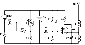
Parts
Part Total Qty. Description Substitutions
C1 1 0.001uf Disc Capacitor
C2 1 5.6pf Disc Capacitor
C3,C4 2 10uf Electrolytic Capacitor
C5 1 3-18pf Adjustable Cap
R1 1 270 Ohm 1/8W Resistor 270 Ohm 1/4W Resistor
R2,R5,R6 3 4.7k 1/8W Resistor 4.7K 1/4W Resistor
R3 1 10k 1/8W Resistor 10K 1/4W Resistor
R4 1 100k 1/8W Resistor 100K 1/4W Resistor
Q1, Q2 2 2N2222A NPN Transistor 2N3904, NTE123A
L1, L2 2 5 Turn Air Core Coil
MIC 1 Electret Microphone
MISC 1 9V Battery Snap, PC Board, Wire For Antenna

  1. L1 and L2 are 5 turns of 28 AWG enamel coated magnet wire wound with a inside diameter of about 4mm. The inside of a ballpoint pen works well (the plastic tube that holds the ink). Remove the form after winding then install the coil on the circuit board, being careful not to bend it.
  2. C5 is used for tuning. This transmitter operates on the normal broadcast frequencies (88-108MHz).
  3. Q1 and Q2 can also be 2N3904 or something similar.
  4. You can use 1/4 W resistors mounted vertically instead of 1/8 W resistors.
  5. You may want to bypass the battery with a .01uf capacitor.
  6. An antenna may not be required for operation.
TDA2822 Stereo Amplifier

·


TDA2822 is a low power stereo Op Amp used in Walkman players and Hearing aids. It can give 250 milli watts output. TDA2822 is an ideal Op amp for low output applications. It is a good choice as a preamplifier in stereo high power amplifier circuits. It has two inputs and two outputs which can deliver 250 milli watts output power. The amplifier circuit with in the IC is well set for noise free operation. Outputs can be directly coupled to the speakers through the decoupling capacitors.

Spy Ear 1.5V Battery operated

·

Amplified Ear

 
Parts:
P1_____________22K Log. Potentiometer (see Notes)
R1,R9__________10K 1/4W Resistors
R2______________1M 1/4W Resistor
R3______________4K7 1/4W Resistor
R4,R7_________100K 1/4W Resistor
R5______________3K9 1/4W Resistor
R6______________1K5 1/4W Resistor
R8_____________100R 1/4W Resistor
C1,C2_________100nF 63V Polyester or Ceramic Capacitors
C3,C6___________1µF 63V Polyester or Ceramic Capacitors
C4_____________10µF 25V Electrolytic Capacitor
C5____________470µF 25V Electrolytic Capacitor
D1___________1N4148 75V 150mA Diode
Q1,Q2,Q3,_____BC547 45V 100mA NPN Transistors
Q4____________BC337 45V 800mA NPN Transistor
MIC1__________Miniature electret microphone
SW1____________SPST Switch (Ganged with P1)
J1_____________Stereo 3mm. Jack socket
B1_____________1.5V Battery (AA or AAA cell etc.)
Device purpose:
This circuit, connected to 32 Ohm impedance mini-earphones, can detect very remote sounds. Useful for theatre, cinema and lecture goers: every word will be clearly heard. You can also listen to your television set at a very low volume, avoiding to bother relatives and neighbors. Even if you have a faultless hearing, you may discover unexpected sounds using this device: a remote bird twittering will seem very close to you.
Circuit operation:
The heart of the circuit is a constant-volume control amplifier. All the signals picked-up by the microphone are amplified at a constant level of about 1 Volt peak to peak. In this manner very low amplitude audio signals are highly amplified and high amplitude ones are limited. This operation is accomplished by Q3, modifying the bias of Q1 (hence its AC gain) by means of R2.
A noteworthy feature of this circuit is 1.5V battery operation.
Typical current drawing: 7.5mA.
Notes:
* Due to the constant-volume control, some users may consider P1 volume control unnecessary. In most cases it can be omitted, connecting C6 to C3. In this case use a SPST slider or toggle switch as SW1.
* Please note the stereo output Jack socket (J1) connections: only the two inner connections are used, leaving open the external one. In this way the two earpieces are wired in series, allowing mono operation and optimum load impedance to Q4 (64 Ohm).

TDA2004 Amplifier Car audio stereo OTL 10W+10W

·

The Circuit TDA2004 Amplifier Car audio stereo OTL 10W+10W.
Volt supply 11V to 14V, Power output 10W+10W#, for Speaker 2-8 ohm.


circuit TDA2004 Amplifier Car audio stereo OTL 10W+10W


PCB TDA2004 Amplifier Car audio stereo OTL 10W+10W 

About this blog

Site Sponsors